
Hydrogen Fuel Cells: A Sustainable Energy Solution
This project explores the potential and provides an overview of hydrogen fuel cells, and how they can unlock the future of hydrogen-powered vehicles.

Abstract
This paper presents the Optimized Hydrogen Liquefaction Machine (OHLM), a cooling system designed for converting hydrogen gas into a liquid state, with a focus on its application in automotive technology. The proposed system is both economical and compact, making it an ideal solution for integrating hydrogen fuel in cars. Comprising three key components—the pre-cooling system, hydrogen cooling system, and HTS (high-temperature superconducting) coil cooling system—the design optimally addresses the challenges associated with hydrogen liquefaction. The pre-cooling system sets the foundation for efficient cooling, followed by the hydrogen cooling system that utilizes O-P (Ortho-Para) conversion to achieve effective liquefaction. The synergy of these components results in a highly economical and space-saving solution — our design is the first hydrogen-powered storage system to cost less than $10,000 for production (our final cost being $9651.76), paving the way for the practical industry-wide implementation of economical hydrogen-powered vehicles with improved sustainability and performance.
Present Technology
Currently, around four-fifths of the global primary energy comes from coal, oil, and gas, which are all not sustainable sources of energy (Fossil fuels, 2017). To supply the energy demands of the rapidly increasing global population, it is essential to transition to a more sustainable energy source that does not negatively affect the environment. Hydrogen, widely touted as a clean and sustainable energy carrier, has garnered significant attention as a potential alternative to conventional fuels, thanks to several factors including its high energy density of up to 39.39 kWh/kg, its high heating value that is triple that of petroleum, and the fact that it has the highest energy content of any fuel by weight. With these factors in mind, it is of little surprise that Goldman Sachs projects the clean hydrogen industry to be worth as much as $10 trillion by 2050.
However, the practical implementation of hydrogen gas as a fuel faces significant hurdles, specifically in cooling and storage; hydrogen liquefaction effectively addresses many of these problems. Liquified hydrogen has an energy density 853 times higher than its gaseous counterpart. This condensed state also allows for more efficient storage and transportation, overcoming some of the major hurdles associated with gaseous hydrogen's volumetric inefficiency. The potential advantages of liquid hydrogen in these domains, as opposed to gaseous hydrogen, are driving ongoing research and development efforts in the hydrogen liquefaction process.
Moreover, advancements in materials are paving the way for innovative solutions. Researchers are exploring novel materials for cryogenic applications; for example, breakthroughs in the design of new materials, including G10 and austenite stainless steel, allow for more effective insulation and transportation for fuel cells.
Meanwhile, the increasing emphasis on green hydrogen production methods, specifically utilizing renewable energy sources, also holds promise for improving the environmental sustainability of hydrogen liquefaction. Electrolysis powered by renewable energy, such as water electrolysis, can produce hydrogen without relying on fossil fuels, aligning with the goal of creating a cleaner energy ecosystem.
However, the foremost impediment in the current state of hydrogen liquefaction technology is its cost. Traditional methods, such as the Claude cycle, Linde-Hampson cycle, or the modified Brayton cycle, involve intricate processes and substantial energy consumption, making them economically burdensome and inefficient in terms of space for a car. The energy-intensive nature of these techniques contributes to a considerable carbon footprint, diminishing the eco-friendly appeal of hydrogen.
The energy efficiency of these methods also leaves much to be desired. The liquefaction process demands extremely low temperatures, typically below -250 °C, to transition hydrogen into a liquid state. Achieving and maintaining such cryogenic conditions necessitates elaborate refrigeration systems, leading to increased operational costs.
Efforts are underway to design compact and decentralized liquefaction systems, particularly crucial for applications like fueling hydrogen-powered vehicles. Miniaturized liquefaction units, equipped with advanced cooling technologies, are being explored to make hydrogen more accessible and practical for diverse applications. The OHLM draws upon the work of ongoing research done by Nam et al, Aasadania et al, and Yuksel et al in order to create more cost-effective hydrogen liquefaction systems for practical use in personal vehicles. We adapted Nam et al’s pre-cooling mechanism using liquid nitrogen and their use of an HTS coil to ensure temperature stability (Conceptual Design of an Aviation Propulsion System Using Hydrogen Fuel Cell and Superconducting Motor, 2021); we used Asadania’s material choices, G10, and a strengthened copper alloy, in our design; and we used miniaturization techniques from Yuksel to create a practical final design. However, none of these papers focused on economizing the cost of hydrogen fuel cells, a key aspect that we aim to address.
History
The history of hydrogen liquefaction traces back to the late 19th century when scientists first began exploring the possibilities of transitioning hydrogen from its gaseous to liquid state. The initial breakthroughs were achieved using rudimentary methods, involving compression and cooling to extremely low temperatures. Notably, in 1898, James Dewar, a Scottish chemist, succeeded in liquefying hydrogen using a combination of compression and cooling called regenerative cooling. He used the Hampson-Linde process to do so; this process is split into four key stages: isentropic compression (elevating the gas pressure and enthalpy), expansion (significantly lowering the gas’s temperature through the Joule-Thompson effect), heat exchange (where the chilled gas cools the next batch of incoming compressed gas), and cycle repetition (back to the top, again, until the gas lowers temperature to sufficiently become liquid).
As our understanding of cryogenics deepened, the early 20th century witnessed the development of more refined liquefaction processes. Claude's cycle, introduced by Georges Claude in 1902, became another pioneering method for large-scale hydrogen liquefaction. These advancements laid the foundation for the industrial use of liquid hydrogen in various applications, including aerospace and scientific research.
In subsequent decades, researchers continued to refine and optimize hydrogen liquefaction technologies. The modified Brayton cycle, introduced in the mid-20th century, further improved the efficiency of the liquefaction process. These technological strides allowed for the production of liquid hydrogen in larger quantities, albeit with inherent challenges such as high energy consumption and environmental concerns.
In the 1960s, General Electric developed a hydrogen-powered fuel cell system for NASA's Gemini and Apollo spacecraft. This marked an early application of hydrogen fuel cells in a real-world setting. However, it was not until the late 20th century that hydrogen fuel cells started to attract attention as a potential solution for automotive propulsion.
The 1990s witnessed the development of hydrogen fuel cell vehicles (FCVs) by various automakers. Toyota, Honda, and other pioneers introduced prototype vehicles, showcasing the feasibility of using hydrogen as a clean and efficient fuel for transportation. In 2004, the first commercial hydrogen fuel cell vehicle, the Toyota Mirai, was unveiled, signaling a new era in the automotive industry.
Despite the technological advancements, challenges persisted. Limited hydrogen infrastructure, high production costs, and concerns about the overall environmental impact hindered the widespread adoption of hydrogen fuel cell vehicles. Currently, city buses are the most promising application as they only need to refuel in one place, thus requiring only one hydrogen refuel station.
Future Technology
OHLM’s cooling system comprises three main components: a pre-cooling system, a hydrogen cooling system, and an HTS (high-temperature superconducting) coil cooling system. To minimize the overall heat load, room-temperature hydrogen gas undergoes pre-cooling to 77K using cost-effective liquid nitrogen before entering the hydrogen cooling system. The cryo-cooler within the hydrogen cooling system then cools the hydrogen to 21 K, funneling it down into the inner tank. The HTS coil, a liquid hydrogen–helium heat exchanger, plays a crucial role in maintaining stable temperatures within the system and feeding liquid hydrogen to the engine. This hydrogen is sent to the blower of the car, providing a total engine capacity of 12 Wh/ml of hydrogen used, a stark upgrade compared to 9.7 wH/ml in gasoline.

Pre-Cooling
A copper pipe undergoes direct cooling through immersion in a pre-cooling system containing liquid nitrogen at a temperature of 77 K. Half of the interior of the copper pipe contains Iron II Oxide (FeO), serving as a catalyst for the ortho-para conversion (OPC) of hydrogen simultaneously during the cooling process. The ortho-para conversion is important because parahydrogen (p-H2) has significant advantages compared to orthohydrogen (o-H2), specifically in heat-related properties such as enthalpy, thermal conductivity, thermal diffusivity, and specific heat capacity. A p-H2 concentration >95% is ensured to reduce the chance of boil-off losses, which is critical to prevent mass vaporization and energy losses. Hydrogen gas, at room temperature, flows through the interior of the copper pipe and undergoes cooling. We anticipate that this gas will come from pressurized containers, which are easily bought online for relatively economical prices. The ortho-para conversion of hydrogen takes place, and the rate of conversion is dependent on the temperature of hydrogen. The target outlet temperature of the pre-cooled hydrogen is 78 K.

The diameter of this pipe will be 12.7 mm, and its thickness will be 1.24 mm. The diameter of the pre-cooling tank will be 175mm; its entire length will be 345mm. The container itself will be made of G10, a carbon composite. G10 is made up of an epoxy resin binder and a glass epoxy composite that contribute to its strength, durability, chemical resistance, and effective insulation (low thermal conductivity value of 7.0 x 10⁻⁴ °C/cm). G10 retains all these characteristics for temperatures as low as -270 °C, rendering it useful for cryogenic applications. The total G10 apparatus of the precooler will be minimal in cost — this entire portion will have costs of under $339, including the Dewar flask apparatus and G10.
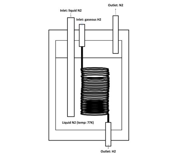
We have designed this system with the assumption that the inlet temperature of the hydrogen gas will be 300 K, and it will come in at 2250 torr. The inlet volume flow will be 45 liters per minute. There is finally a pipe for N2 to be released once it becomes a gas.
The requisite materials for this would include copper piping, of dimensions 183.65x1x12.77mm. Using current standard rates, we approximate that this part of the system would cost $7100 to manufacture, most of which is devoted towards the OP converter; and it will have running costs of $143.12 to replace the liquid nitrogen.
Hydrogen Cooling
The hydrogen cooling system is carefully engineered to address various aspects of heat management, consisting of a liquid nitrogen shield layer, buffer layers, a cooling pipe, and an O-P converter (Ortho-Para converter). The outer wall is equipped with a 175x175x250mm liquid nitrogen shielding layer, strategically placed to minimize radiant heat within the hydrogen cooling system. Additionally, multiple buffer layers are incorporated in the inner tank, effectively mitigating convective heat loss. The O-P converter, a critical element, again contains FeO as a catalyst for the ortho-para conversion of hydrogen, with the rate contingent on the temperature of hydrogen.
To facilitate the comprehensive analysis of the system, specific parameters and conditions are considered. The temperature distribution of the inner wall, outlet temperature, and the pressure and flow rate of hydrogen liquefied through the O-P converter play pivotal roles. The hydrogen cooling system's O-P converter has an outer diameter of 100 mm and a total length of 75 mm. Featuring 20 pins, each with a thickness of 2 mm and a length of 40 mm, the converter optimizes heat transfer within minimal volume. Operating at an input flow rate of 0.55 lpm, the converter efficiently transforms hydrogen from an inlet temperature of 78.6 K to an outlet temperature of 21.3 K, highlighting its critical role in the controlled cooling process of the overall system.
To minimize contact of the liquid N2 with air to prevent condensation of atmospheric oxygen on the liquid N2, our model implements a Dewar flask around the liquid nitrogen containers. This will ensure that oxygen can not enter the container while also allowing gaseous N2 to escape. The gap between the two vessels in the Dewar flask will have a high vacuum, providing good thermal insulation and reducing heat conduction, and convection. The Dewar flask will trap the eventual gaseous N2 above the liquid N2 and hold it at high pressure. This will increase the boiling point of the liquid N2, allowing it to be stored for longer periods. In case of excessive vapor pressure, the Dewar flask will have pressure-relief valves to release the gas automatically.

HTS Coil
The HTS coil system consists of a current lead, a support structure, and a copper plate. To ensure optimal performance, the support structure also employs G10, effectively minimizing conduction heat load and maintaining the stability of the HTS coil. The copper plate, serving as the heat transfer pathway between the HTS coil and the heat exchanger, is constructed using OFHC (oxygen-free high-conductivity copper) for enhanced cooling efficiency due to its high heat transfer rate. To further reduce thermal load, an HTS wire is employed as the current lead.
The coil comprises six turns, and the heat exchanger's dimensions are 300 × 140 mm, with a pipe diameter of 12.7 mm and a thickness of 1 mm. It operates with a current of 150 A, featuring an inlet pipe temperature of 23 K. The current lead reaches a temperature of 80 K, while the support maintains a temperature of 300 K.
The cost of this system is $4806; most costs are for the oxygen-free copper. With the other two sections, it brings us to a grand total of $9651.76 as our cost.
Breakthroughs
The widespread adoption of hydrogen fuel faces several significant roadblocks, which preclude the usage of OHLM. While advancements in technology have addressed some challenges, various barriers persist, hindering the seamless integration of hydrogen as a mainstream energy source.
One primary roadblock is the production of hydrogen itself. The most common methods of hydrogen production involve natural gas reforming and electrolysis. Natural gas reforming emits carbon dioxide, undermining the environmental benefits of hydrogen as a clean energy source. On the other hand, electrolysis relies on electricity, often sourced from fossil fuels or other renewable energy sources, contributing to the overall carbon footprint and raising the question if it makes sense for hydrogen to be the primary power if we just have to use another energy source to extract it.
The transportation and storage of hydrogen to fueling stations pose additional hurdles. Hydrogen has a low energy density, requiring significant storage and transportation infrastructure. Existing pipelines designed for natural gas are unsuitable for hydrogen due to their unique properties, necessitating extensive modifications or the construction of new infrastructure. The development of efficient and safe hydrogen storage technologies, such as advanced composite materials or liquid carriers, is crucial for overcoming these logistical challenges. While OHLM allows cars to store LH2 easily, the bulk transportation of the fuel is another matter entirely.
Another roadblock lies in the high upfront costs associated with establishing a hydrogen infrastructure. Building hydrogen production facilities, storage tanks, distribution networks, and refueling stations requires substantial investment. Governments, industries, and investors must collaborate to allocate resources and incentivize the development of a comprehensive hydrogen ecosystem. Without financial support and a clear regulatory framework, the transition to hydrogen may be economically unviable for many stakeholders. We have seen, however, an early example of a moderately successful infrastructure base for hydrogen fuel in California, proving that it is possible to create that infrastructure base given sufficient investment into the field. A potential solution to increase hydrogen refuel station prevalence is to use electrolysis at refueling stations to convert electricity from the grid into hydrogen. If electrolysis is used, there may have to be an increase in electricity generation, though the increase would be small, since hydrogen can be produced during off-peak times.
The lack of a standardized regulatory framework is another significant obstacle. Governments and international bodies need to establish consistent regulations and safety standards to facilitate the global adoption of hydrogen. Harmonizing codes and standards would streamline the development of hydrogen technologies and infrastructure, ensuring interoperability and enhancing public confidence in the safety of hydrogen applications.
Design Process
We considered incorporating a thermal energy recovery system into our hydrogen cooling system design with the aim of harnessing and repurposing excess heat generated during the cooling process. The concept was to capture this thermal energy and convert it into usable electrical power or redirect it for other heating purposes. While this idea sounded promising in theory, we refrained from its inclusion due to practical constraints. The current technology and system dynamics may not efficiently facilitate the recovery and conversion of the generated heat. The intricate nature of the hydrogen cooling process, coupled with challenges associated with converting excess heat into useful energy, made implementing this feature impractical at the moment.
Another feature we contemplated was an adaptive cooling control system, designed to dynamically adjust cooling parameters based on real-time conditions and demands. This system could optimize the cooling process, ensuring energy efficiency and precise temperature control. However, we opted against its incorporation due to the complexity it introduced, and the resultant increased prices that consumers would face. Seamless integration would demand advancements in control algorithms and sensor technologies.
Finally, we explored the possibility of introducing an advanced hydrogen purity monitoring system to ensure the quality of the liquefied hydrogen. This system would continuously monitor hydrogen purity levels and adjust processing parameters to maintain high-quality liquid hydrogen. While this feature seemed beneficial, the current limitations in sensor technologies and the complexity of precisely controlling hydrogen purity within the stringent conditions of the liquefaction process presented significant hurdles. Achieving real-time monitoring with high accuracy and implementing precise control measures would require advancements in both sensor capabilities and process control methodologies, making the inclusion of this feature impractical for our current design.
Consequences
An anticipated future where OHLM is adopted would not be without its drawbacks. The environmental impact of mass hydrogen production could lead to a situation where hydrogen fuel cells are just as ‘dirty’ as fossil fuels, even if the invention gets adopted. Additionally, the many millions of jobs in the fossil fuel industry would almost certainly be disrupted with the widespread emergence of hydrogen technology, as we are already seeing in the status quo. The fossil fuel industry is deeply entrenched in global economies, providing the primary source of energy needs, particularly in transportation and power generation. This shift could lead to economic challenges for countries heavily dependent on fossil fuel exports and trigger workforce adjustments within the industry.
Nonetheless, let us not forget that the alternative to the adoption of renewable fuels is furthering climate change, which is far worse in its impact given that warming temperatures and more severe storms are an existential threat to humanity. OHLM holds the potential to usher in a green energy transition. By leveraging hydrogen as a clean and sustainable energy carrier, it could replace traditional fossil fuels, offering a promising solution to reduce carbon emissions and address climate change concerns. Additionally, integrating such systems into the automotive sector could revolutionize transportation, providing a cleaner alternative and overcoming limitations associated with electric vehicle range and battery technologies. It could also spur more investment into other forms of renewable energy, leading to greater institutional funding from the automotive industry and other stakeholders in the transportation sector.
If you liked this article, have any questions, or want to provide any feedback, please email me (natank929@gmail.com) or check out my <a href="https://www.linkedin.com/in/natan-kramskiy-1a3999294/">LinkedIn</a> to connect further.
Sample Web Pages
Here is a mockup of a potential website if we were to really make this product: https://www.figma.com/file/7Ho9YZIgZzyqcnMckp3PR7/Figma-Website-Template---Landing-Page-(Free)-(Community)?type=design&node-id=0-88&mode=design
Bibliography
Ritchie, Hannah, Pablo Rosado, and Max Roser. “Fossil Fuels.” Our World in Data, January 5, 2024. https://ourworldindata.org/fossil-fuels.
GenH2 Staff. “Defining the Hydrogen Economy from A to Z: D is for Density.” Hydrogen A-Z Series, January 20, 2022. https://genh2hydrogen.com/blog/defining-hydrogen-from-a-to-z-3/#:~:text=At%20standard%20atmospheric%20pressure%20and,through%20phase%20change%20is%20incredible
Manoharan, Yogesh, Seyed Ehsan Hosseini, Brayden Butler, Hisham Alzhahrani, Bhi Thi Fou Senior, Turaj Ashuri, and John Krohn. “Hydrogen Fuel Cell Vehicles; Current Status and Future Prospect.” Applied Sciences 9, no. 11 (January 2019): 2296. https://doi.org/10.3390/app9112296.
Qiu, Yinan, Huan Yang, Lige Tong, and Li Wang. “Research Progress of Cryogenic Materials for Storage and Transportation of Liquid Hydrogen.” Metals 11, no. 7 (July 2021): 1101. https://doi.org/10.3390/met11071101.
Michael Lapides, Insoo Kim, David Fishman, Chao Ji. “Green Hydrogen: The next transformational driver of the Utilities industry.” Equity Research, September 22, 2020. https://www.goldmansachs.com/intelligence/pages/gs-research/green-hydrogen/report.pdf
“Online Course and Simulator for Engineering Thermodynamics.” https://direns.mines-paristech.fr/Sites/Thopt/en/co/cryogenie.html.
Hydrogen Solutions. “LIQUEFACTION.” https://cryostar-hydrogen-solutions.com/liquefaction/.
“Hampson–Linde Cycle.” In Wikipedia, August 17, 2023. https://en.wikipedia.org/w/index.php?title=Hampson%E2%80%93Linde_cycle&oldid=1170776139.
Chang, Ho-Myung, Bo Hyun Kim, and Byungil Choi. “Hydrogen Liquefaction Process with Brayton Refrigeration Cycle to Utilize the Cold Energy of LNG.” Cryogenics 108 (June 1, 2020): 103093. https://doi.org/10.1016/j.cryogenics.2020.103093.
Aasadnia, Majid, Mehdi Mehrpooya, and Bahram Ghorbani. “A Novel Integrated Structure for Hydrogen Purification Using the Cryogenic Method.” Journal of Cleaner Production 278 (January 1, 2021): 123872. https://doi.org/10.1016/j.jclepro.2020.123872.
Dzhafarov, T. D., and S. Aydin Yuksel. “Porous Silicon-Based Direct Hydrogen Sulphide Fuel Cells.” Journal of Nanoscience and Nanotechnology 11, no. 10 (October 2011): 9012–15. https://doi.org/10.1166/jnn.2011.3456.
Nam, Gi-Dong, Le Dinh Vuong, Hae-Jin Sung, Seok Ju Lee, and Minwon Park. “Conceptual Design of an Aviation Propulsion System Using Hydrogen Fuel Cell and Superconducting Motor.” IEEE Transactions on Applied Superconductivity 31, no. 5 (August 2021): 1–7. https://doi.org/10.1109/TASC.2021.3064526.
“Energy Density.” https://chemistry.beloit.edu/edetc/SlideShow/slides/energy/density.html.
Energy.gov. “Hydrogen Storage.” https://www.energy.gov/eere/fuelcells/hydrogen-storage.
Riaz, Amjad, Muhammad Abdul Qyyum, Arif Hussain, and Moonyong Lee. “Significance of Ortho-Para Hydrogen Conversion in the Performance of Hydrogen Liquefaction Process.” International Journal of Hydrogen Energy, Special Issue on HYPOTHESIS XVI, 48, no. 68 (August 8, 2023): 26568–82. https://doi.org/10.1016/j.ijhydene.2022.09.022.
“G-10/FR4 - Current Inc,” May 20, 2017. https://currentcomposites.com/industrial-laminates/g10-fr4/, https://currentcomposites.com/industrial-laminates/g10-fr4/.
East, Sara. “G10: Your Go-To Material for Electronics, Robotics, and Mechanical Applications.” SendCutSend (blog), January 10, 2024. https://sendcutsend.com/blog/g10-your-go-to-material-for-electronics-robotics-and-mechanical-applications/.
Egan, Max. “G10 Material: Complete Guide to Epoxy Glass Composite.” Atlas Fibre, November 26, 2023. https://www.atlasfibre.com/g10-material-complete-guide-to-epoxy-glass-composite/.
“Vacuum Flask.” In Wikipedia, January 22, 2024. https://en.wikipedia.org/w/index.php?title=Vacuum_flask&oldid=1198054311.
“Cryogenic Storage Dewar.” In Wikipedia, September 30, 2023. https://en.wikipedia.org/w/index.php?title=Cryogenic_storage_dewar&oldid=1177987298.